GOLFMK8
GOLFMK7
GOLFMK6
GOLFMKV

W6050 only this thread

dr_ehabatif

Passed Driver's Ed
Location
egypt
what is ment by the new canbus and how it is installed ? is it just plug and play like the one that comes with our devices? or will iy be more advanced?

i dont know really how is the condition of the steering wheel buttons with our current devices as in the video of the new canbus interface all are working perfectlyhow is the condition with the current? does the mute button work? can i answer or rejet a acall with the phone button? can i us the steering wheel phone button to turn on the phone in the device while listening to cd or radio for example?

importantly when i m listening to radio can i change the channels or frequancies with the steering wheel buttons. and when i m listening to cd can i change the track or fast or rewind the current song with the steering wheel buttons?

i know that the mfd doesnt show the track name or the radio chanel ? what is its condition with the phone?

can i switch between aux, dvd, radio etc using the steering wheel button?


i need ur help in these issues please and i guss it will be very helpfull for many others making their decision


ur soon reply will be much appreciated guys
thanks
 

GTIMKV20

APR Stage I
Location
MA
Car(s)
VW GTI MKVI
ahh damn, so bummed about the lack of firmware update... would have been too easy I guess. If somebody rips their unit apart I'd like to see how tough it would be to install the new canbus unit.. if it has soldering involved I am out... but if you just have to bust open the radio and unplug one unit and pop the next one in and then put it back together I'd be down. Thanks for the updates and clarification Oskar!!
 

Jayro

Old Newbie
Location
Scotland
For Ylian

Hi Ylian I have tried your edit to reposition the road speed reading on the display, and my results are as follows :-
Just looking at the map with no Navigation programed in, the reading is off position, and the compass is displayed in the middle of box in question.
When a Navigation is programed in, the road speed is repositioned where the Compass heading was, and the compass dissapear's off the screen.
As this is not the correct behaviour, any ideas what I have done wrong, and a "howto" to correct it please.
( I think although I have changed the text, I have not changed the enbedded values, is that possible ?) I did not use "edit" from the menu when I opened the file, I just extracted it out to the desktop, modified it and put it back.
 

boosho

Has no Clue
Location
Melbourne
Car(s)
MKV GTI Pirelli DSG
Also does anyone know of a good pro to install in melbourne, i will try to do it myself but it will be my first time i attempt to install a head unit on my own. So i would like to have a back up option Just in case.
 

Ylian

Passed Driver's Ed
Location
Oregon, USA
Hi Ylian I have tried your edit to reposition the road speed reading on the display, and my results are as follows :-
Just looking at the map with no Navigation programed in, the reading is off position, and the compass is displayed in the middle of box in question.
When a Navigation is programed in, the road speed is repositioned where the Compass heading was, and the compass dissapear's off the screen.
As this is not the correct behaviour, any ideas what I have done wrong, and a "howto" to correct it please.
( I think although I have changed the text, I have not changed the enbedded values, is that possible ?) I did not use "edit" from the menu when I opened the file, I just extracted it out to the desktop, modified it and put it back.

Hi Jayro. This problem would have driven me nuts. The bug where the speed indication is displayed on top of the map (Look carefully at pictures here) happens only when you update to iGO8r3 and only when no route is programmed in. It's because of a bug in "data.zip version 9c", I proposed a fix earlier in this thread (middle of page), but there is another proposed fix by WRZ$ here. Maybe this other fix would work for you.

I used WinRAR 3.80 to perform this change and have both extracted and added the file back and used the direct edit feature. Both techniques work.

Ylian
 

Angedet8

New member
Location
Melbourn, Victoria
Car(s)
VW Passat
Blue connector on main harness wire

Does anyone know what the small blue connector on the main harness wire is for? It is circled with an arrow pointing at it?
 

Attachments

  • WD6050_Blue connector.jpg
    WD6050_Blue connector.jpg
    42.9 KB · Views: 1,939

FJ_Steve

Age shall not weary him
Location
Perth

He is one ungrateful little (but tall) old man huh mrx :fighting0030:

Wonder who he will ask to fit his next radio :happyanim:
Come on guys...I'm not feeling the love here.

Oh...and who will fit it? hmmm....Maybe VW?:lol:
 

Jayro

Old Newbie
Location
Scotland
For Angedet8

The small blue connecter is a mini iso connecter, and it is for items such as a CD changer, ipod VW fit, phatbox and xlink ect.
Fit in the head unit in the yellow lined box in the pic. and connect whichever device you have to the quadloc connecter.
The head unit will then see the connected device in the CD selection as cd changer
 
Last edited:

buckets

Ready to race!
Location
Melbourne
Also does anyone know of a good pro to install in melbourne, i will try to do it myself but it will be my first time i attempt to install a head unit on my own. So i would like to have a back up option Just in case.

From all the DIY's installation looks pretty straight forward there boosho. I'll be doing my own when the unit arrives, so if you want to come over and check it out you're more than welcome. PM me.

This will be my first VW but have installed a couple of dozen HUs in other models with great success.

Craig
 

dr_ehabatif

Passed Driver's Ed
Location
egypt
question

The small blue connecter is a mini iso connecter, and it is for items such as a CD changer, ipod VW fit, phatbox and xlink ect.
Fit in the head unit in the yellow lined box in the pic. and connect whichever device you have to the quadloc connecter.
The head unit will then see the connected device in the CD selection as cd changer

can this blue thing be connected to a usb flash memory or hard disk?
 

timj

Ready to race!
Location
Perth WA 6055
Car(s)
08 GTI
Come on guys...I'm not feeling the love here.

Oh...and who will fit it? hmmm....Maybe VW?:lol:

Awe, u know we wub u big fella :wub:

I'm sure Mav will be happy your going the way of RNS, just hope your missus caves into your request/grovelling etc :bellyroll:
 

Ylian

Passed Driver's Ed
Location
Oregon, USA
Breaking open the WD6050

I just spent the last few hours opening the WD6050 apart (Pictures here). Before I get started I want to say that I put it all back together and it works perfectly again. I also want to note that I am a software guys, not hardware, but the story ends well. I had three goals today: Check functioning of the rear view camera, open up the unit and takes notes & pictures, install the SMA bend for the GPS antenna.


Rear-view camera: I wanted to figure out how the read-view camera feature worked before considering installing one. My digital camera (Canon SD750) has an video out feature and so, could easily be used as a temporary video source. I started by pulling the unit out of the car and connecting my digital camera to the rear camera input of the device. The unit detected the presence of the video signal and activated the "Camera" feature in the main menu. When I turned on the video source, it did not automatically switch to the rear-view camera, so having a permanent video source is ok. I then started the car and placed it in reverse and yes, the unit changed to the rear-view camera. Going back to park and it switched back to the previous selected source. All as expected. I question if you can power the camera from the rear white lights because the camera would turn on after the rear gear is engaged and may not work. With this unit, I would likely want the rear camera powered all the time when the car is running. It is nice be able to select the rear-camera regardless of the gear position, but have it show up automatically when in rear.


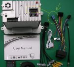
Breaking the device open: I then took the device home and started pulling it apart. Taking pictures and notes as I went along. There are 7 boards in this unit: Main, Display, Tuner, GPS, DVD, SD slots and CAN-BUS decoder.

  • The main board also contains the AM/FM tuner in addition to connectors to all the other boards. It clearly has flash parts, power supply, etc. It has 3 free connectors.
  • The display board is in the front and seems to control buttons, display, touch screen, etc.
  • The tuner board is built to handle 3 types of tuners. I have the north American version, but it had markings for DMB-TH and DVB-T tuner components. Only one of the 3 tuners can be installed at any given time.
  • GPS board is small and just connects between the GPS antenna and the main board. Looks like off the shelf board.
  • DVD disk reader is as expected, also off the shelf component.
  • SD card slots is the simplest board. Just the two slots and a single connector to the main board.
  • Finally, the CAN-BUS decoder, located completely under the device, it's the hardest to get to and the most disappointing. In this picture, it's the blue board on the right. It seems to be a very simple board that converts CAN-BUS into a very simple signaling connector (Batt, Acc, Break, Light, Back, Key, Bus-, Bus+). There is likely no way this board would be able to handle anything more complex than detecting the rear gear is engaged. It's almost certain that this unit will need another CAN-BUS decoder if it wants to do anything more.
The main board has 3 free connectors labeled CON8 (5 pins), CON3 (5 pins) and CON1 (2 pins). Because of the location of CON1, I suspect it's just a connector to power the optional fan. I will have to research the remaining 2 connectors, they are located at the right place, near the central processing unit and internal beeper (yes, the unit has a beeper). Access to CON5 and CON8 does not require opening the full device. You can see and reach them by removing the front only. I will scan and post my diagrams in the next few days and see if I can find anything interesting about these connectors. I could not find any removable flash parts. The spare connectors may be JTAG or something.


I saw the built-in microphone. I did not change it, but it does seem very possible. You do have to know what you are doing. Certainly not for everyone. You do not need to open the main unit to hack the microphone, only the front needs to be opened. Still, there is a lot of care that needs to be taken to separate the display board from the display itself. The power, touch and display connectors need to be removed and reconnected very carefully.

Lastly, I added the GPS SMA bend and it's a good thing. The normal antenna connector does have to bend quite a bit. I posted most of the pictures of today's activities. When I reinstalled the unit, I turned the key and the unit stayed off... I was VERY worried for 10 seconds because it always turned on automatically then I turn the key. I then pushed the volume button in and it turned on. Just a little scare for a while.

Ylian
 
Last edited:

buckets

Ready to race!
Location
Melbourne
Hey Ylian,

You wouldn't have happened to take a pic or two of the mic? Am getting my unit on the next shipment and think I'll have a crack at the mic extension. But wouldn't mind seeing what I'm up against first.

Craig
 

Ylian

Passed Driver's Ed
Location
Oregon, USA
Microphone replacement

For microphone replacement, the microphone is at the complete lower left of this picture.


It's also located on the upper left of this picture. It's a black circle.


It's soldered on the top side, nothing special to report. On the top picture you can see the LCD power (2 pins, white connector), touch (small ribbon), video (large ribbon) and a black ground connector.

Access to the front is not difficult, 4 screws will detach the front from the main unit. Two ribbon cables will connect the main unit to the front, I would not detach them since they are long and will not get in the way. Separating the video board from the LCD required 6 screws and disconnect 4 connectors. The board is also snapped on, so you need to unsnap it.

Ylian
 
Top